JAFITA / The continuous route

Moving Walks

Moving walks provide a continuous surface for people travelling across a building or between levels on an inclined route. Horizontal installations can reduce the effort of a long concourse journey. Inclined installations can support a retail circulation plan that includes specifically compatible shopping trolleys.

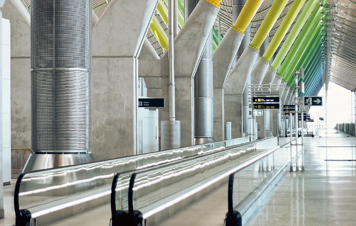
Horizontal moving walk with glass balustrades inside an airport terminal
A horizontal route through an airport concourse · application reference.

JAFITA coordinates moving-walk supply through a project-specific equipment and manufacturing route. The selection starts with the journey length, level difference, passenger behaviour and any approved cart use. Pallet width, speed, inclination, support geometry and exposure are then defined as one configuration. They should not be assembled from unrelated catalogue ranges.

Product overview and scope of supply

A moving walk consists of a circulating passenger surface and its drive, guidance, structural supports, handrails, balustrades, landing transitions, controls and protective devices. The detailed specification identifies the actual construction. Pallet and belt systems are distinct arrangements, and parts or trolley suitability should not be transferred between them.

JAFITA’s supply discussion establishes the equipment type, manufacturer, technical package and coordination responsibilities. Building supports, floor recesses, adjacent finishes, drainage, electrical supply, public-route protection and local acceptance must be assigned alongside the machine itself.

Where a continuous moving surface is not appropriate for a user or load, the building needs a clearly identified alternative route. Review Passenger Elevators and the surrounding fixed circulation space as part of that plan.

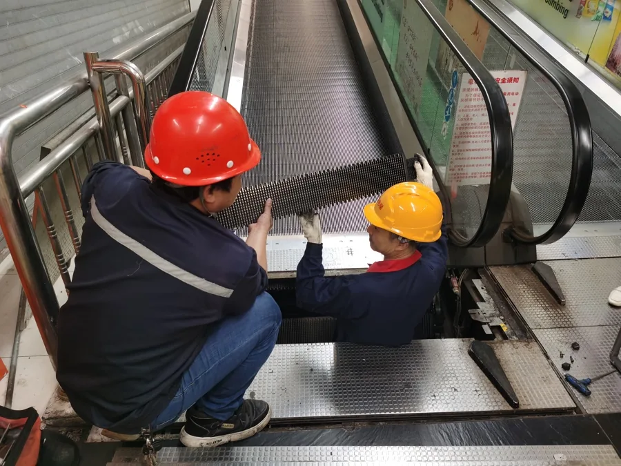
Two technicians lifting a pallet from an open moving-walk entrance section
A pallet assembly removed at the landing · technical reference.

Applications and operating conditions

Long concourses and terminals: Define the complete journey, including the approach, exit and walking route alongside the equipment. Luggage, groups stopping to orient themselves and queues at nearby entrances can affect flow. A long machine is useful only if its access and discharge points fit the route people actually take.

A continuous moving walk can also create a barrier across a concourse: passengers cannot leave at an intermediate shop, gate or corridor unless the layout provides a proper exit there. Map those destinations before choosing the moving length. Dividing the route into separate machines may preserve a needed crossing, but adds boarding transitions and machinery ends. The comparison should account for both the journey assisted and the cross-routes retained.

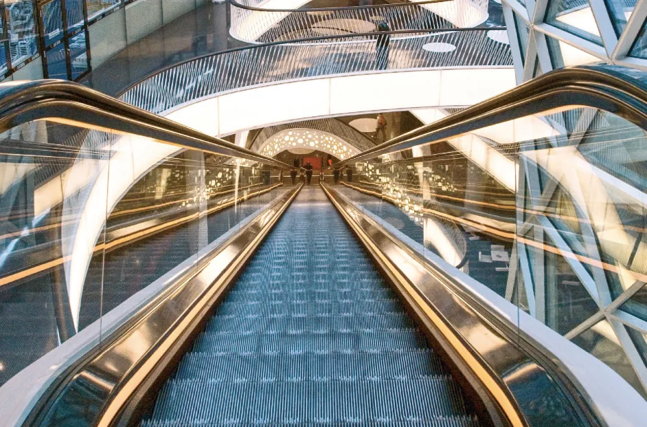
Inclined moving walk connecting levels in a modern atrium
An inclined route connecting building levels.

Multi-level retail: Begin with the proposed trolley fleet and how customers reach and leave the moving walk. The trolley, moving surface and transition geometry must be assessed together. A trolley that works on a flat floor is not automatically suitable for an inclined moving walk.

Weather-exposed links: Describe water exposure, wind, temperature, dust and corrosive conditions. Long equipment routes may cross different building environments. The drainage and enclosure strategy should follow the whole installation, including the landings and machinery spaces.

Product range and configurations

Route or configuration Principal task Decision that needs attention
Horizontal route Assist travel over distance on the same general level Useful moving length, entrances, parallel walking space and intermediate destinations
Inclined route Connect levels on a continuous surface Rise, permissible inclination, transitions and total floor area occupied
Opposing parallel units Provide a route in each direction Separation, access at both ends and circulation when one unit is unavailable
Same-direction parallel units Serve a defined directional flow Demand pattern, onward capacity and the alternative return route
Pedestrian-only operation Transport users within the specified operating rules User mix, luggage and entrance guidance
Approved trolley operation Carry suitable carts with their users Exact trolley design, retention, loading and exit compatibility

Project selection also distinguishes commercial duty from public-transport duty. Neither description is established by pallet width alone. Operating hours, load profile, maintenance access and required documentation determine the appropriate equipment review.

Performance and engineering features

Useful length is more meaningful than overall length. Overall equipment length includes landing and return arrangements. For journey planning, identify where passengers actually step on and off, then compare the moving section with the complete walking route.

Transitions control the handover to the building. Entry and exit geometry must suit pedestrians and any permitted trolley. Clear discharge space matters because people and carts need time and room to move away from the moving surface.

Why a trolley needs more than the right width

On an incline, gravity tends to move a loaded trolley down the slope. Compatible travelator castors provide a defined holding mechanism rather than relying on an ordinary free-running wheel. Depending on the design, running discs enter the pallet grooves so braking surfaces can engage, or a sensing disc triggers wheel locking. The mechanisms and their compatibility differ between castor manufacturers, so confirm the exact trolley model.

The engineering task is to confirm engagement, stability and a controlled return to rolling at the landing for the actual trolley and moving walk. Wheel spacing, wheelbase, underbody clearance, loaded mass and the position of the load all belong in that review. A bulky load projecting outside the trolley basket can create a different clearance problem even when the trolley itself fits.

Inclined moving walk connecting levels in a modern atrium
Inclined moving-walk application · illustrative context. Trolley and castor compatibility require confirmation for the selected system.

Record the approved trolley and castor identification with the equipment documents. A later fleet change or substitute wheel can alter the interface without changing the apparent trolley size. The operator therefore needs compatible replacement parts and a maintenance responsibility for the trolleys as well as the moving walk.

Operation should follow demand. Continuous operation and permitted demand-responsive strategies have different implications for passenger detection, acceleration and quiet periods. Compare them against the site’s operating pattern and selected equipment. Energy estimates need stated assumptions about hours and loading rather than a universal savings percentage.

Separate travel assistance from a time-saving promise

For an illustrative horizontal moving section 50 m long, a standing passenger travelling at an assumed 0.5 m/s spends 100 seconds on that section: 50 m ÷ 0.5 m/s. That calculation excludes the approach, any boarding delay and the exit. It does not show whether the complete trip is faster than the available fixed walking route; that requires a comparison using the actual users and routes.

This distinction is useful for terminals and exhibition buildings. Some users value reduced walking effort, while others need direct access to intermediate destinations. Define which task the moving walk serves before measuring success only in seconds. The figures above are a planning illustration, not a JAFITA product rating.

Review Your Route and Trolley Interface

System architecture and key components

In a pallet-type arrangement, linked pallets circulate through tracks within the supporting structure. The drive and transmission move the band; the return arrangement maintains its designed path and tension. Handrails travel alongside the passenger surface, while the controller coordinates operation and safety status.

Two technicians lifting a pallet from an open moving-walk entrance section
The pallet, landing and return-area interface.

Comb assemblies and landing plates manage the transition to the fixed floor. Their condition and compatibility matter to both pedestrian use and any approved trolley interface. Guards, balustrades and handrail entry protection address boundaries around moving components.

Use Escalator and Moving-Walk Components to discuss pallets, rollers, chains, handrails and other replacements. Provide the original unit and part identification. A nominal pallet width does not identify its profile, axle arrangement or compatible comb.

Technical specifications

The technical schedule should identify the selected model and define its measurement datums. “Length” can mean horizontal projection, distance between supports or the distance passengers travel on the moving surface; those measurements answer different questions and must remain distinguishable.

Parameter Unit or description Required interpretation
Equipment type Pallet or belt, as offered Establishes the actual running-surface and component architecture
Horizontal projection and overall length mm or m State the end points and distinguish machine envelope from useful journey length
Vertical rise mm or m Measure between defined finished-floor datums
Inclination Degrees Confirm the permitted geometry for the proposed equipment and use
Nominal pallet or belt width mm Distinguish the passenger surface from overall installation width
Rated speed m/s Assess with user behaviour, transitions and any trolley use
Duty profile Hours/day and demand description Identify continuous demand, peak periods and operating direction
Trolley compatibility Identified trolley model and assessment Include mass, dimensions, wheel design and intended loading
Electrical supply V, phase, Hz and load information Confirm main, lighting and accessory supply requirements
Supports and reactions Locations and kN Identify end and any intermediate support requirements
Environment Temperature and exposure specification Define protection, drainage and service conditions

The final schedule should also state the operating modes, safety configuration and document package. Any numerical transport-capacity estimate needs its method and occupancy assumptions.

Dimensions and building requirements

Reserve the complete equipment envelope, landing areas and maintenance access. For a long horizontal installation, check whether expansion joints, structural movement or changes in floor level intersect the proposed route. The structural engineer and equipment designer must agree how those interfaces are handled.

Inclined moving walk connecting levels in a modern atrium
Incline, horizontal projection and the complete installation are different measures.

For an inclined route, consider both the horizontal projection and the moving-surface length. An ideal straight line rising 4.00 m at an assumed 12° projects approximately 18.82 m horizontally, while the line itself is approximately 19.24 m long. These follow 4.00 ÷ tan(12°) and 4.00 ÷ sin(12°), respectively. Actual end transitions, machinery and landing interfaces require the selected equipment drawing; neither geometric result is the total installation length or confirmation of a permissible product configuration.

The building must provide appropriate landing finishes, clear circulation, power and environmental protection. Recesses should not become unintended collection points for water. Where intermediate supports are required, coordinate their positions with the space below and the construction sequence.

For a long installation, an intermediate support is a structural connection with a specified reaction and elevation. It cannot be moved to clear a doorway below without reviewing the truss arrangement. Ask the equipment designer and building engineer to resolve support locations together before ceiling, retail or services layouts are fixed.

The Project Planning review should also establish how long sections reach the installation position and how future major components can be removed.

Safety features and applicable standards

Safety review covers the moving surface, handrail, braking and control arrangements, landing transitions, emergency stops, required guards and building clearances. The selected equipment’s protective functions and applicable evidence must be listed in the project submission.

Trolley use is allowed only for the assessed combination and operating conditions. Do not infer that an approved shopping trolley arrangement permits wheelchairs, pushchairs or arbitrary luggage carts. The operator’s guidance must identify permitted use and direct other users to the appropriate route.

ISO 8103-1 covers safety requirements for new escalators and moving walks, including pallet and belt types. Destination rules may instead or additionally reference EN 115-1, ASME A17.1/CSA B44 or national requirements. Establish the adopted rules and approval process before final selection; naming a standard is not evidence that a particular machine has been accepted.

Horizontal moving walk with glass balustrades inside an airport terminal
Handrails, balustrades and the fixed walking route.

Design and available options

Glass or solid balustrade treatments, handrail colours, decking, landing finishes and lighting should support clear movement through the building. On a long route, consistent direction information helps users identify the correct entrance before they reach the moving surface.

Inclined moving walk connecting levels in a modern atrium
Material and lighting relationships in an atrium.

Any requested monitoring, building-management connection or operating display needs a defined interface and supported equipment version. Do not assume that a generic control contact provides a complete remote-monitoring service. Optional functions, supplied accessories and items by other contractors should be listed separately in the order.

Material selection must consider cleaning, visible wear and environmental exposure. A public concourse with luggage has different contact patterns from a retail installation carrying approved shopping trolleys. State the intended cleaning process and the adjacent floor materials before finish approval. In a trolley application, dirt or damage affecting the wheel-to-pallet interface is also a functional issue. Keep decorative treatments and cleaning products compatible with the approved passenger surface and trolley system.

Inclined moving walk connecting levels in a modern atrium
Inclined moving-walk application · illustrative context. Trolley and castor compatibility require confirmation for the selected system.

Quality control and testing

The inspection plan should confirm the equipment identity, geometry, running-surface components, drive arrangement and selected environmental provisions against the approved schedule. Visible workmanship, finish consistency and the condition of landing and handrail assemblies are relevant final checks.

Where trolley operation is proposed, the project needs evidence for the specified trolley and moving-walk combination. A successful unloaded run cannot establish loaded trolley compatibility. Define the responsible test party, load conditions, acceptance basis and record before procurement is finalized.

Installed support conditions, landing clearances and the complete operating sequence require site verification. See Inspection and Testing and Quality Management for the distinction between factory evidence and acceptance of the completed installation.

Application scenarios and matching references

Horizontal moving walk with glass balustrades inside an airport terminal
Terminal connection · application reference.

Terminal connection scenario: A long concourse connects a central hall to a distant gate area. The planning exercise compares a single continuous route with a layout that preserves access to intermediate destinations. The review also considers luggage, cross-traffic and the walking route during maintenance.

Inclined moving walk connecting levels in a modern atrium
Level connection · application reference; trolley approval is project-specific.

Retail trolley scenario: A store connects sales levels while customers retain their shopping trolley. The equipment review starts with that trolley, its loaded mass and wheel system, then examines approach space and the transition at the receiving floor.

These illustrative scenarios address different passenger and load conditions. For a delivered-project comparison, request a Relevant Project Reference with the moving-walk configuration, operating conditions and JAFITA’s actual supply or service role identified.

Technical documents and downloads

JAFITA’s corporate brochure identifies moving walks within its commercial and public-transport offering. A project enquiry should request the selected manufacturer’s current datasheet, general arrangement, support reactions, power schedule and operating description.

For a trolley application, include a written compatibility basis and the trolley identification in the document register. For an existing unit, obtain the correct parts information and maintenance instructions using its nameplate and configuration. Generic drawings should remain planning references until the project revision is approved.

Request Moving-Walk Drawings · Request a Technical Document List

Hands reviewing building drawings on a desk
Plans, datums and support interfaces for equipment coordination.

Delivery and lifecycle support

Long equipment requires coordination between the factory’s section plan and the building’s access route. Confirm the delivery envelope, package masses, unloading area, temporary openings, storage and the agreed installation sequence. Split delivery can make access possible but adds defined assembly and verification work at the site.

Two technicians lifting a pallet from an open moving-walk entrance section
Pallet removal requires retained access at the landing.

Installation Support provides the agreed equipment coordination for the qualified site team. Handover should identify operating rules, permitted carts, acceptance records, cleaning limits and maintenance responsibility. Use Technical Training to align staff understanding with the delivered system.

After-Sales Support begins with traceable identification. Preserve pallet or belt details, handrail profile, chain and roller specifications, controller version and any subsequent modifications. Maintenance access must remain available after surrounding retail or terminal fit-out changes.

Moving-walk FAQs

Inclined moving walk connecting levels in a modern atrium
Inclined moving-walk application · illustrative context. Trolley and castor compatibility require confirmation for the selected system.

Can every moving walk carry shopping trolleys?

No. Send the proposed trolley’s full technical data, not only basket dimensions. A supplier’s statement that a castor is intended for travelators does not by itself approve the complete loaded trolley on a particular moving walk. Keep the written compatibility basis with the equipment and fleet records so it can be checked after replacements or modifications.

Is an inclined moving walk a substitute for an accessible elevator?

Do not assume so. Accessibility requirements and the needs of users who cannot safely use the moving surface must be addressed separately. Include an appropriate alternative route in the building plan.

Why is nominal width different from the space required?

Nominal width describes the moving passenger surface. The complete installation also includes balustrades, handrails, structure, clearances and service interfaces. Use the approved overall drawing to reserve building space.

Does a longer moving walk always produce a better route?

Consider the exit first. A longer moving section can deliver passengers to a bottleneck more continuously without increasing the capacity of the onward corridor. Observe or estimate the receiving space and traffic there before extending the machine. The route still needs to work when maintenance closes the equipment.

Can the equipment cross a building expansion joint?

This requires an engineering review of the structural movement, support arrangement and equipment limits. Show the joint and anticipated movement in the initial drawings rather than discovering the interface after production.

Can we change trolley wheels to reduce maintenance costs?

Treat a different wheel or castor as a compatibility change. Match the approved identification or obtain a documented review covering the new assembly and complete trolley. Similar wheel diameter or fixing dimensions do not establish the holding and release behaviour required on the moving walk.