JAFITA / The path of travel

Elevator Guide Systems

Guide rails, shoes, brackets and their connections establish the path followed by the elevator car and counterweight. Their geometry and installation condition affect movement, while their relationship with the structure and safety equipment gives them a role beyond ride comfort.

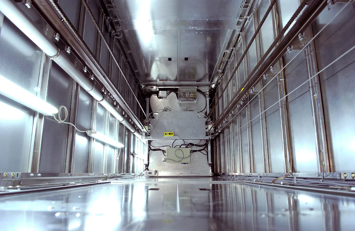
Interior of a metal-clad lift shaft showing guides, chains and lighting
Rails, supports and connected equipment within a compact lift shaft · technical reference.

JAFITA coordinates guide-system enquiries for new equipment packages and identified replacements. Requirements may cover rails and jointing parts, supports and clips, sliding shoes, roller guides or designated accessories. Rail section, material, accuracy requirements, shoe interface and support design are confirmed for the particular installation; there is no universal rail size for a given elevator capacity.

Product Overview and Scope of Supply

A rail package may include specified lengths, fishplates, bolts, clips and related supports. A guide-shoe enquiry may concern an assembly, a matched insert or a manufacturer-defined service part. The order needs a clear schedule because rails, supports and shoes do not automatically arrive as one complete set.

JAFITA can coordinate identification, drawings and source information. The responsible designer must confirm rail selection, loading and support arrangement; the local installation party must verify site conditions and complete the required installation and acceptance work.

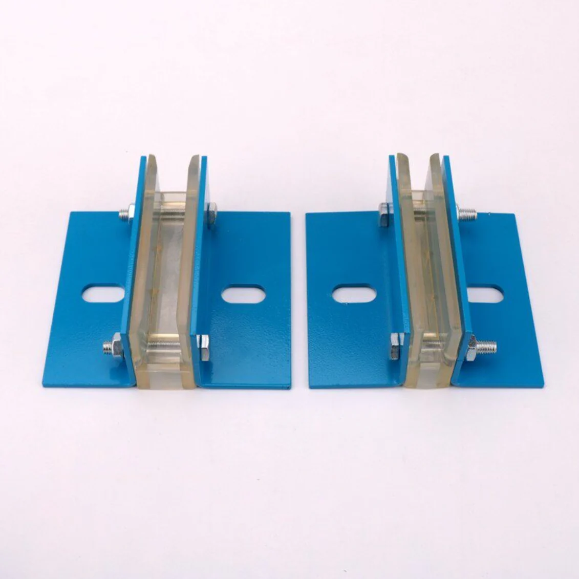
Pair of sliding guide shoes with blue mounting plates
A guide-shoe assembly is a distinct item in the supply schedule.
Guide rails, suspension ropes and steel supports viewed inside an elevator shaft
Guidance, suspension and the available shaft envelope · technical reference.

Applications and Operating Conditions

Passenger equipment needs guidance appropriate to speed, car proportions and ride expectations. Freight service may add eccentric or concentrated loading that changes the forces carried through the car frame and guides. Counterweight guidance has its own configuration and loading considerations.

State the shaft conditions, travel, available support structure, environment and maintenance provisions. Dirt, corrosion, damaged surfaces and unsuitable maintenance materials can affect the guide system. An enquiry for recurring noise should describe when it occurs and include the qualified maintainer’s findings rather than assuming the shoe is the sole cause.

Guide-System Configurations

Item or arrangement Selection purpose Key dependency
Car guide rails Define the car’s guided path and relevant structural interfaces Load cases, supports and safety-gear relationship
Counterweight rails Guide the specified counterweight arrangement Counterweight design, supports and applicable safety equipment
Sliding guide shoes Use a specified sliding interface against the rail Rail blade, insert material and maintenance requirements
Roller guides Use a matched rolling arrangement Rail interface, loading, speed and manufacturer limits
Brackets, clips and jointing parts Connect the rail system and supporting structure Drawing, rail profile, fastening arrangement and building substrate

Choose the family from the equipment design and service conditions. A roller guide is not automatically an upgrade for an installation designed around a different interface. The entire proposed change needs review.

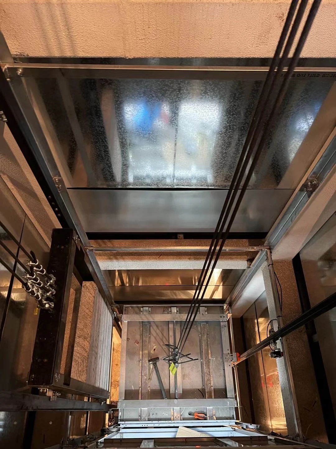
Guide rail joint, brackets and cables inside an unfinished lift shaft
Identify the actual rail function, joint and fixing arrangement.

Identify car and counterweight guidance separately

Some documents describe “main” and “auxiliary” rails, but those labels are not a sufficient specification. Identify whether the rail guides the car, the counterweight or another designated assembly. Car and counterweight systems can have different sections, shoes, loads and safety-device relationships. A lighter-looking counterweight rail must not be selected for the car simply because its blade fits an available shoe.

For component orders, keep the rail, joint parts and guide assemblies grouped by that actual function. This avoids combining the right quantities into the wrong installation set and preserves the information needed for later spare-part identification.

Performance and Engineering Features

Guide rail joint, brackets and cables inside an unfinished lift shaft
01 / Joint continuity

Rail quality and the installed riding path are different checks

A rail can meet its manufacturing specification while the assembled path still has a discontinuity at a joint or an alignment issue between supports. The guide shoe encounters the installed path, not the rail’s delivery certificate. That is why rail dimensions, joint geometry, installation alignment and final ride assessment answer different questions.

Height differences at rail joints and rail verticality can contribute to vibration or noise, so replacing a guide shoe does not necessarily correct a path problem. Record whether a disturbance occurs at a repeatable position or changes with loading; that gives the qualified team a better basis for deciding what to inspect.
Interior of a metal-clad lift shaft showing guides, chains and lighting
02 / Rails and their support span

Rail section and bracket spacing must be considered together

The rail spans between its supports. For a given load and arrangement, changing that unsupported span changes its deflection behavior. A section that works with one bracket layout is therefore not automatically suitable where the building forces supports farther apart. Increasing rail size and adding supports can be alternative design responses, but they have different material, installation and building-interface consequences.

Guide-system engineering practice likewise treats section choice and bracket spacing as a connected decision. The project’s calculations and actual fixing substrate determine the answer. Ordering a heavier rail without reviewing the brackets, clips and structure leaves part of the load path unresolved.

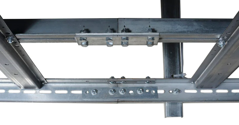
Steel lift frame crossmembers and bolted connections
03 / Frame and load transfer

The guide cannot compensate for every car-frame condition

Eccentric loading changes the forces and moments transferred through the Car Frame into its guidance. An issue that appears when a trolley is parked at one side may therefore need a loading and frame review, as well as inspection of the guides. A softer or harder guide component should not be chosen solely to mask that behavior.

Ride quality is the outcome of compatible components, the completed geometry and operating conditions. Define the intended result and the evidence needed to assess it before changing the guidance arrangement.

System Architecture and Load Relationships

The car’s guidance elements attach to the frame and interact with the rails. Rails connect through their joints and supports to the building. Where a safety gear acts on the rail, its permitted rail characteristics are part of the system design.

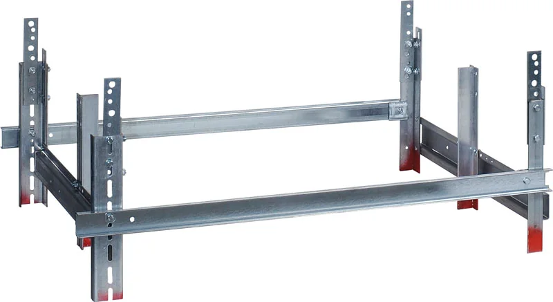
Bolted steel support frame with slotted uprights
Connected steel members and bolted fixing interfaces.

Review Cabins and Car Frames for mass and load distribution, and Safety Components for the relevant rail interface. The relationship is especially important when changing cabin weight, guide-shoe type or safety equipment during modernization.

The connections also have distinct jobs. Fishplates join adjacent rail lengths; brackets position and support the system relative to the building; clips connect the rail to those supports according to the designed fixing arrangement. Treating these as generic hardware overlooks their role in joint continuity, force transfer and any permitted movement required by the design. Their drawings and load basis belong with the rail specification, not in an unrelated fastener order.

Technical Specifications

Guide-system field Unit or description Review purpose
Rail identity Manufacturer, section designation and applicable standard Establishes the specified product
Rail geometry Blade and base dimensions, length and holes in mm Matches shoes, joints and supports
Material and finish Grade, manufacture and working-surface requirements Connects the rail to its design and device limits
Accuracy requirements Drawing and relevant tolerance specification Controls geometry and joint quality
Support arrangement Locations, spacing and fixing details Establishes structural interfaces
Loads N or kN, direction and design load cases Supports engineering selection
Guide shoe Model, blade interface, insert or roller identity Establishes the correct contact arrangement
Car or counterweight data Mass in kg, speed in m/s and layout Defines the application
Safety gear where applicable Exact model and permitted rail conditions Confirms the protective-system relationship
Quantities Rail lengths, joint sets, brackets and accessories Reconciles the package with the installation

A profile name is useful identification, but it does not replace the approved material, dimensional and application requirements.

Dimensions, Supports and Building Interfaces

The layout should identify rail centerlines or designated working references, distance between guides, bracket positions and the relationship to car and counterweight equipment. Structural supports must be designed for the required loads and actual building substrate.

For replacement work, record existing rail geometry, jointing and support details before requesting an alternative. A new section may affect shoes, safety gear and available shaft space. Project Planning helps bring the equipment requirements and building survey into the same review.

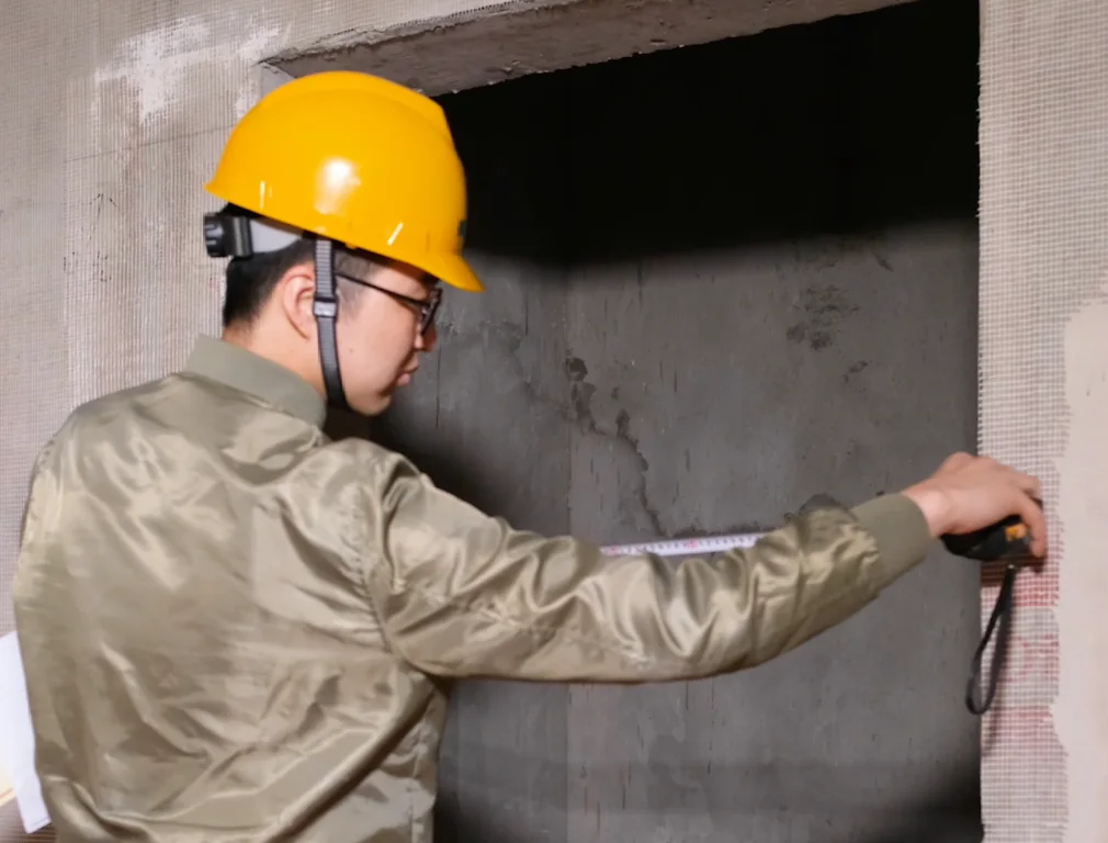
Worker measuring an unfinished elevator opening with a tape measure
Site measurements connect the equipment layout to the building.
Overspeed governor with a yellow wheel mounted on a steel bracket
Protection and guidance must be reviewed as connected systems.

Safety Relationships and Applicable Standards

Guide rails are part of an engineered installation, and relevant product standards do not eliminate the need for application calculations and site verification. ISO’s catalogue identifies ISO 8100-33:2022 as the successor to the withdrawn ISO 7465:2007. The project should identify the actual standard and edition required, including any destination-specific requirements.

Where safety gear relies on the rail, use the rail characteristics permitted by the selected device’s documents. Avoid treating a different surface condition, material or section as equivalent merely because a guide shoe appears to fit. Installation and maintenance belong with appropriately qualified parties.

Materials, Shoe Versions and Accessories

Pair of sliding guide shoes with blue mounting plates
Complete sliding-shoe assemblies.

Potential choices include the selected rail grade and finish, support arrangements, guide-shoe model and approved inserts or rollers. Manufacturer-defined maintenance requirements must be retained when an item is replaced. Different guide constructions can require different working-surface conditions.

Specify whether a shoe order includes its mounting assembly or only a service insert. Record the material and geometry of the actual replacement, not just its color. Any proposed coating or corrosion-protection treatment must be reviewed for the working surfaces and connected safety devices.

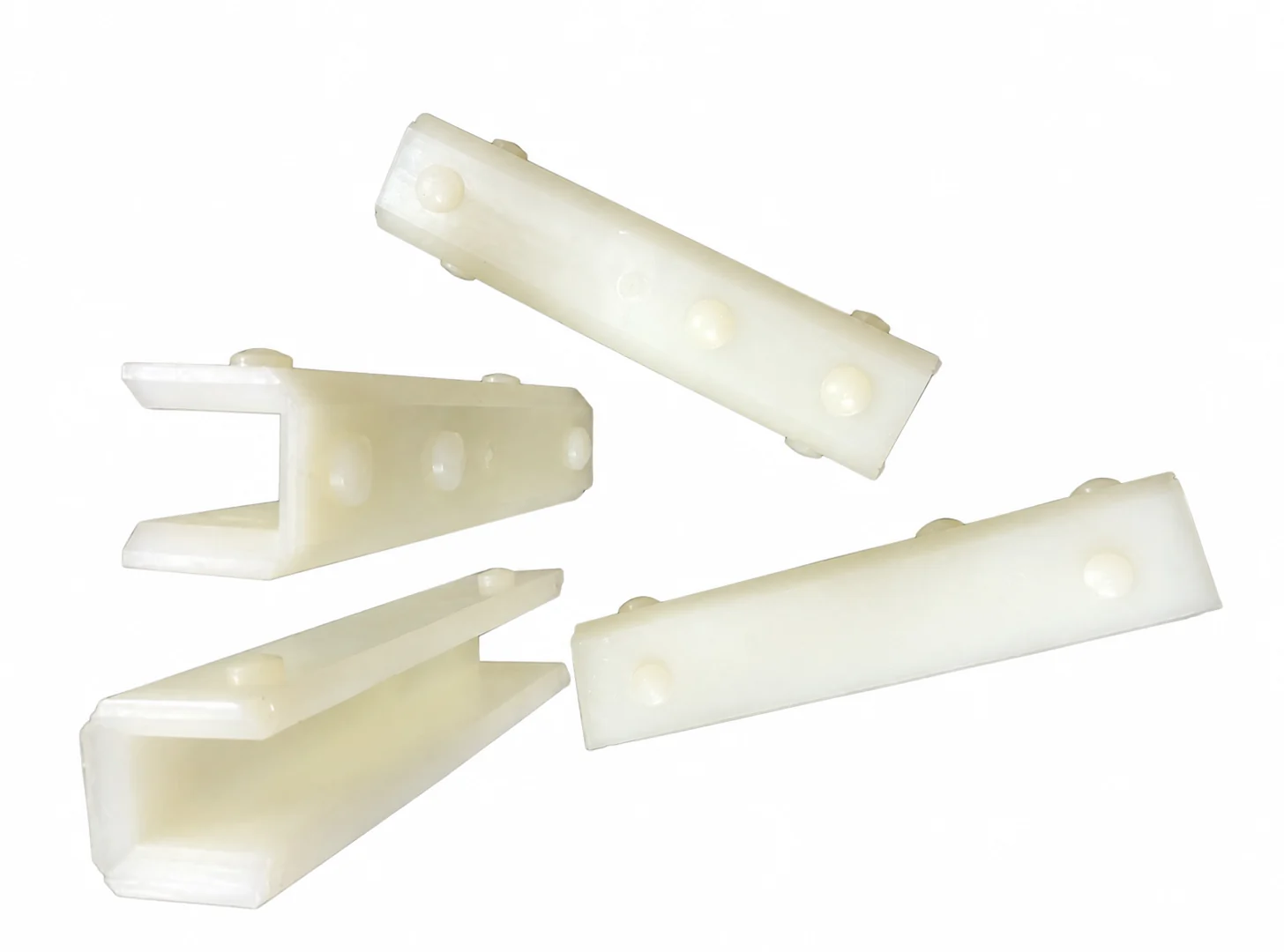
Four white U-shaped guide shoe liners on a workbench
Separate guide-shoe inserts · material and geometry require identification.

A sliding insert’s material and contact shape affect its working relationship with the rail. A roller guide adds roller, bearing and supporting elements with their own permitted loading and motion. Neither family can be evaluated simply by checking the mounting-hole pattern. Retain the selected manufacturer’s working-surface and maintenance requirements, especially where Safety Gear uses the same rail. A change that appears beneficial to the guide can be unsuitable for another device acting on that surface.

Quality Control and Inspection Information

The agreed checks should relate to rail identity, lengths, joint interfaces, straightness and surface condition, together with the specified records. Shoe and accessory checks should establish the actual model and correct interface. Inspection criteria and evidence must be defined in the order rather than inferred from a catalogue adjective.

For a new guide-system package, define the required dimensional, material and condition records against the selected rail specification and accessory schedule. See Quality Management and Inspection and Testing.

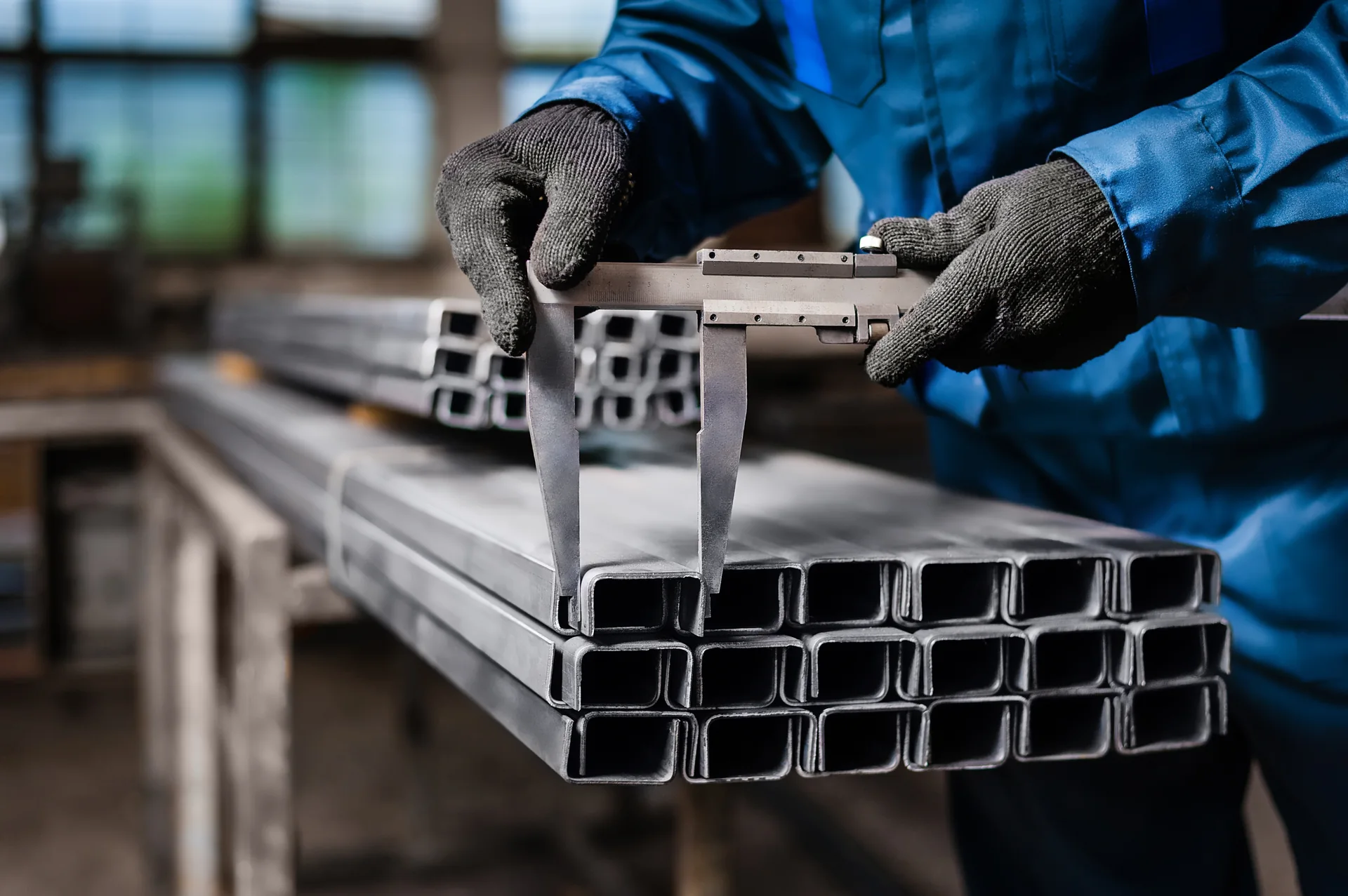
Gloved hands measuring a rectangular metal section with a caliper
Check the specified geometry and the relevant dimensional record.
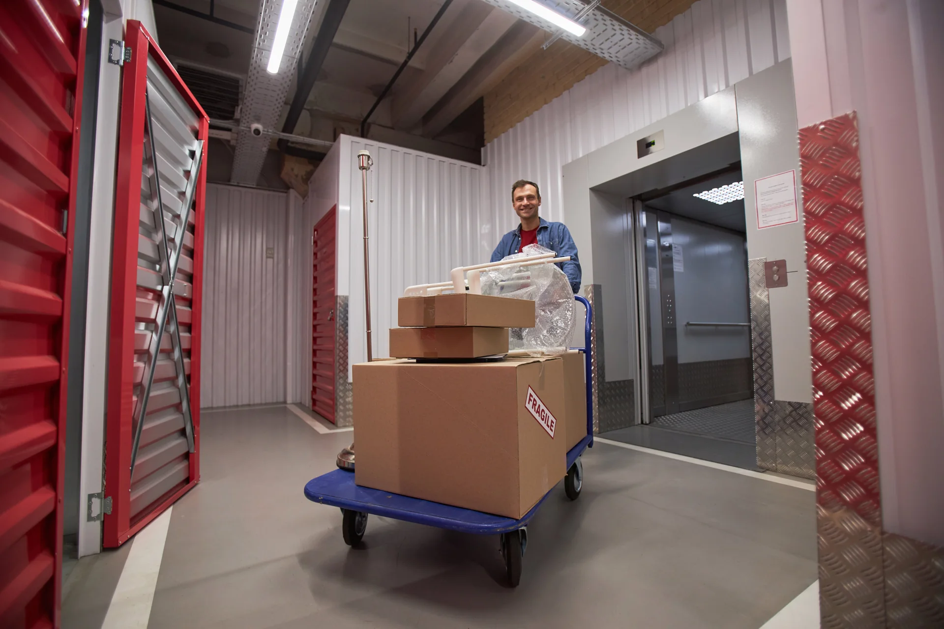
Worker moving a cart of boxes beside an open freight elevator
Trolley position changes the load distribution · application reference.

Reference Applications and Diagnostic Context

An illustrative freight installation reports movement that changes when a trolley is parked near one side of the car. A useful investigation reviews the load position, car frame, guidance and support condition together. Ordering a stiffer-looking shoe without that context can leave the underlying issue unresolved.

Request reference information relevant to the equipment duty, rail arrangement and actual supply or service scope. The comparison should identify the car or counterweight application, support layout and documented work performed.

Technical Documents and Drawings

Useful records include the rail and joint drawing, guide layout, bracket schedule, material and tolerance specification, shoe datasheet and applicable maintenance information. Request any necessary relationship with the safety-gear documentation at the same time.

For existing equipment, original drawings should be compared with a qualified survey where modifications or uncertain dimensions exist. Documents for a similar rail family are not a substitute for an identified installed section.

Request Guide-System Drawings Request Product Information

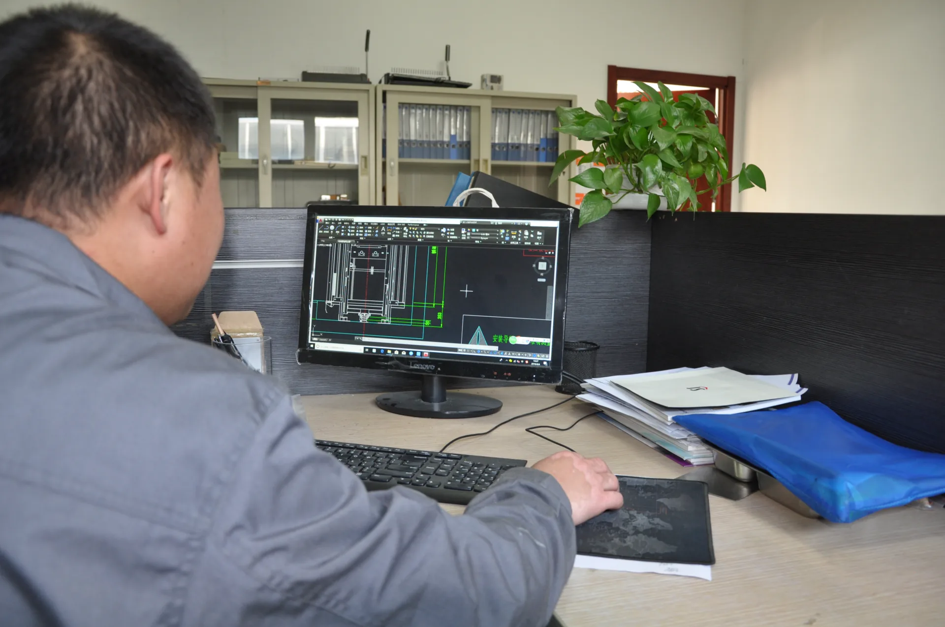
An engineer reviewing a lift CAD drawing at a workstation.
Guide layout and component drawings · company archive.

Delivery and Lifecycle Support

Guide rail joint, brackets and cables inside an unfinished lift shaft
Keep rail ends, joint interfaces and the installed system identifiable.

Rails need handling and packing that protect their straightness, ends and working surfaces. Keep lengths, joint parts and matched accessories identifiable. The receiving team should have suitable storage and a way to record visible damage before the installation sequence begins.

Agree packaging and site coordination through Installation Support. Handover should retain the rail and shoe identities and their approved maintenance information. Technical Training and After-Sales Support can be scoped to the actual supplied system.

Guide-System Questions

Four white U-shaped guide shoe liners on a workbench
Color and width alone do not identify an insert.

Can rail size be chosen from elevator capacity alone?

No. The frame geometry, load distribution, support arrangement, travel conditions and relevant safety loads also influence selection.

Will roller guides remove all vibration?

No. Rail geometry, joints, support condition, car balance and other equipment can contribute. Select guides as part of the complete system and investigate the observed cause.

Can new rail lengths be mixed with existing rails?

Only after the section, material, joint interfaces, working surfaces and application are confirmed by the responsible technical party. A similar designation is insufficient by itself.

Can a worn insert be ordered by color and width?

Those details help identification but do not establish material or compatibility. Supply the shoe maker, model, rail interface and original part information.